

 Academic Frontier
The latest review of Chemical Reviews: Can a small step in the development of graphite-phase carbon nitride g-C3N4 become a major step in a sustainable development strategy?
QQ Academic Group: 1092348845
Detailed
In the 21st century, energy shortage and environmental pollution have become major issues affecting the development of human society. The use of photocatalysts to convert inexhaustible solar energy into energy that can be directly used by human beings, and to completely mineralize and degrade various organic and inorganic pollutants is a current direction of research on renewable clean energy.
Among many photocatalysts, the graphite phase carbon nitride gC 3 N 4 with a unique structure has become a research hotspot due to its good photocatalytic performance. Compared with other photocatalysts, its advantages are very outstanding: it can absorb visible light, has good thermal stability and chemical stability, and is non-toxic, rich in source, and simple in preparation and molding process.
Recently, the article published by Wee-Jun Ong of Monash University and others in Chemical Reviews integrates the research progress of gC 3 N 4 materials and its application in catalysis; introduces the problems and challenges faced in the research process and has been adopted Optimization method; finally, the future development direction and application prospect of gC 3 N 4 are prospected. This document inspired researchers to continuously improve the technology and open the door to the next generation of gC 3 N 4 research.
Detailed description of literature and text:
Part 1 gC 3 N 4 structure and preparation method
C 3 N 4 has a total of five structures, which are α phase, β phase, cubic phase, quasi-cubic phase and graphite-like phase. As shown in Figure 1 below, the structure of the graphite-like phase (gC 3 N 4 ) is the most stable, it has a layered structure similar to graphite, and contains two allotropes. These two allotropes have different positions due to different nitrogen-containing pores, resulting in different stability. Kroke et al. Found through density functional theory (DFT) calculations that (b) 3-s-triazine is the structural unit The connected gC 3 N 4 has the best stability. Therefore, the gC 3 N 4 used in recent studies has the structure shown in (b).

Figure 1: Two chemical structures of gC 3 N 4 : (a) using triazine as a structural unit to form gC, and (b) using 3-s-triazine as a structural unit.
In nature, no natural gC 3 N 4 crystal has been found so far . Therefore, gC 3 N 4 mainly comes from experimental synthesis. Selecting appropriate carbon and nitrogen sources, gC 3 N 4 can be obtained under certain reaction conditions . Commonly used reactants include melamine, melamine chloride, cyanamide, dicyandiamide, urea, etc. At present, the commonly used preparation methods are: high temperature and high pressure synthesis, physical and chemical vapor deposition, electrochemical deposition, solvent thermal polymerization, pyrolysis of organic matter waiting. Wherein the thermal polymerization can be easily changed by adding other substances or adjusting the reaction conditions gC . 3 N . 4 structure, thereby improving the gC . 3 N . 4 photocatalytic properties, is gC . 3 N . 4 Study of the most commonly used synthetic methods.
Figure 2 is the temperature required to obtain gC 3 N 4 using different precursors . For example, to prepare gC 3 N 4 using cyanamide as a precursor , the required temperature is 550 ℃.

Figure 2: The temperature required to prepare gC 3 N 4 by thermal polymerization using different precursors . Black, blue, white, red, and yellow spheres represent C, N, H, O, and S atoms, respectively.
Figure 3 shows the preparation of gC 3 N 4 by using cyanamide as a precursor , and combining thermogravimetric analysis (TGA) and X-ray diffraction to obtain the intermediate product of the reaction. The reaction process includes polymerization and polycondensation. First of all, cyanamide molecules form dicyandiamide and melamine at 203 ℃ and 234 ℃ through polycondensation reaction. Both still exist, but after reaching 390 ℃, the structure of melamine begins to rearrange, forming a 3-s-triazine structural unit. When the temperature reaches 520 ℃, the 3-s-triazine structural unit is further polycondensed to form gC 3 N 4 . Finally, when the temperature exceeds 600 ℃, the stability of gC 3 N 4 begins to decline. When it exceeds 700 ℃, gC 3 N 4 disappears.

Figure 3: (a) XRD patterns of intermediate products obtained at different temperatures when cyanamide was used as the precursor to synthesize gC 3 N 4. (B) Formation of energy changes of each reaction product.
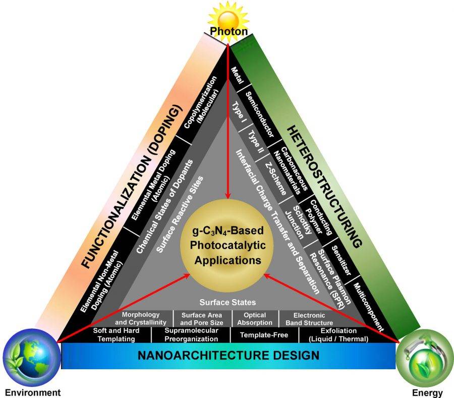
Part 2 gC 3 N 4 material optimization
In the application process of gC 3 N 4 materials, the main challenges are: electron-hole recombination is too fast, quantum efficiency is low, specific surface area is not large enough, etc., which greatly limits its practical application effect. Therefore, researchers at home and abroad have proposed a variety of methods for improving gC 3 N 4 materials, such as precursor, preparation process, preparation method optimization, nanometer modification, chemical doping modification, and physical compound modification. Sex and so on.
Figure 4 shows the values of specific surface area and band gap energy of gC 3 N 4 materials obtained by selecting different precursors and synthesis parameters . The selected examples show that through this approach, the different energy band structures, electronic properties and surface areas of gC 3 N 4 materials can be effectively controlled , so it is feasible to use this method to improve the photocatalytic performance.

Figure 4: Specific surface area and band gap energy values of gC 3 N 4 materials obtained from different precursors and synthesis parameters (partial table)
So far, the main method to make g-C3N4 nanometer is template method or non-template method. The template method includes the hard template method and the soft template method. Here, the hard template method is used as an example. Figure 5 shows the synthesis of mesoporous g-C3N4 using SiO 2 at 20-80 nm as a hard template. The mesoporous structure increases the specific surface area of g-C3N4, increases the number of electron-capturing sites, and slows the recombination of electron-hole pairs, enabling it to overcome the adverse effects of a slight increase in the band gap and improve photocatalytic performance.

Figure 5: (a) Ordered synthesis of mesoporous g-C3N4: First , the C 3 N 4 -SiO 2 composite was synthesized by SiO 2 nanosphere hard template and CNNH 2 at 800K , and then the hard template was removed by HF. , (b) having a diameter of 20 nm is of SiO 2 on a hard template obtained of SiO 2 , (C) - (E) diameters were 30 nm to, 50 nm, 80 nm, wherein (b) (e) Since the hole diameter is too Large, it can be seen that some adjacent holes are connected together.
Chemical doping modification can change the electronic structure of g-C3N4 well, thereby improving the photocatalytic performance. The doping of gC 3 N 4 mainly includes metal doping and non-metal doping. Metal element doping mainly includes Fe, Ni, Cu, Zn, etc. It is generally believed that doping a small amount of metal ions into the gC 3 N 4 structural unit can make it a shallow potential trap for photo-generated electron-hole pairs, extending electrons The recombination time with holes improves the photocatalytic performance of gC 3 N 4 . Non-metallic doping mainly includes O, N, P, S, B, F, etc. It is generally believed that the C, N, and H elements in the 3-s-triazine structural unit are replaced by these non-metal elements to form gC 3 N The lattice defect of 4 , so as to achieve the effect of efficient separation of photogenerated electrons-holes, which ultimately leads to the improvement of photocatalytic performance.
Taking FIG. 6 as an example, it belongs to O doping in non-metal doping. During the experiment, mild H 2 O 2 was first used to pre-treat the melamine to form MHP (cyanamide-hydrogen peroxide) through the generated hydrogen bonds. Then, continuous nitrogen flow was used while calcining at 550 ℃ to obtain supramolecules. Aggregates.

Figure 6: (a) Schematic diagram of the synthesis of oxygen-doped gC 3 N 4 photocatalyst, (b) The calculation and analysis of the lowest binding energy shows that the oxygen atom replaces the nitrogen atom at the 1, 3 position and the carbon atom at the 4, 5 position, (c) the oxygen doping to optimize cell structure, the light absorption rate and enhance the efficiency of charge separation, (d) the results show that the band gap decreases, (e) the original gC . 3 N . 4 and the oxygen doping gC . 3 N . 4 different Of charge density. The charge density near the carbon atoms drops sharply, and the charge density near the nitrogen atoms rises sharply.
Physical compound modification is currently the most convenient improvement method. The selected composites are mainly metal materials (such as ordinary metals, precious metalized and bimetallic materials), semiconductor materials (such as metal oxides, metal hydroxides, metal sulfides, metal composites, synthetic compounds, metal organic frameworks and others ), Graphene-like materials (such as graphene, graphene oxide, carbon nanotubes, etc.), polymer compounds (such as P3HT, PANI, etc.). After compounding, the photocatalytic performance of g-C3N4 has been improved to some extent. Moreover, g-C3N4 and the composite substance are not simply physical mixtures, but fully contact to form a heterojunction. Due to the difference in the conduction band and valence band positions of the two, the electrons or holes generated by g-C3N4 photoexcitation are transferred to the conduction band or valence band of the composite, the electron holes are separated, and the recombination rate is reduced, which can be used more efficiently Active particles produced by light excitation. The addition of the compound can also give the catalyst some unique advantages, such as g-C3N4 and Fe3O4, Bi25FeO40 composite magnetic, which facilitates the recycling of photocatalyst.
Taking Figure 7 as an example, in g-C3N4-PEDOT-Pt ternary nanocomposites, PEDOT-PSS (styrene sulfonic acid) was first prepared. Because of its extremely high solubility, g-C3N4- was prepared in the second step Adding ethylene glycol to PEDOT prevents PEDOT from falling off and improves the conductivity and stability of PEDOT. Finally, in-situ photoinduced technology is used to deposit Pt nanoparticles on g-C3N4-PEDOT to obtain g-C3N4-PEDOT-Pt ternary Nanocomposites.

Figure 7: Schematic diagram of the synthesis of g-C3N4-PEDOT-Pt ternary nanocomposite and the process of electron-hole separation.
Part 3 : Application of materials in photocatalysis
The unique structure of graphite carbon nitride gC 3 N 4 determines its wide application in the field of photocatalysis. At present, gC 3 N 4 is mainly used in the production of hydrogen by photolysis of water, photocatalytic reduction to reduce CO 2 emissions during hydrocarbon combustion , photocatalytic decomposition of pollutants and sterilization and disinfection.

Figure 8: Development direction: 1. Water decomposition, 2. Reduce the carbon dioxide content in the environment, 3. Sterilization and disinfection, 4. Environmental purification

Figure 9: Schematic diagram of hydrogen evolution by photolysis of water. The use of gC 3 N 4 as a photocatalyst under light radiation has an effect on the evolution of H 2 and O 2 during water separation . The total reaction formula is: H 2 O → H 2 + 1 / 2O 2 . Wherein the oxidation reaction is the H 2 O + 2H + → 2H + +. 1 / 2O 2 , the reduction reaction of 2H + + 2E - → H 2 .

Figure 10: Schematic diagram of the principle of photocatalytic reduction to reduce the CO 2 produced during the combustion of compound fuel . Among them, gC 3 N 4 photocatalyst is used to make CO 2 and water form different solar fuels under different light radiation .

Figure 11: Photocatalytic degradation of pollution and disinfection of bacteria. Schematic diagram of the process of using gC 3 N 4 as a photocatalyst to degrade pollution under different light radiation.

Figure 12: Mechanism of bacterial inactivation under photocatalysis. (a) (b) is the inactivation mechanism of CNRGOS 8 and RGOCNS 8 structures under aerobic environment . (c) (d) is the inactivation mechanism of CNRGOS 8 and RGOCNS 8 structures under anaerobic environment . The efficiency graph of using photocatalyst to kill virus in prefabricated samples is (B) (C), and the two respectively show the relationship between the bacterial density under aerobic and anaerobic conditions with time.
Literature link: Graphitic Carbon Nitride (gC 3 N 4 ) -Based Photocatalysts for Artificial Photosynthesis and Environmental Remediation: Are We a Step Closer To Achieving Sustainability? (Chem. Rev., 2016, DOI: 10.1021 / acs.chemrev.6b00075)
Information source: material cattle
- Previous: [Biodaily] 2D material
- Next: Bioactive Materials|离子