【Work introduction】
Lithium metal is considered to be one of the most promising anode materials, but the irreversible loss of the SEI layer requires a relatively excessive amount of metal lithium, which inevitably increases the total weight and causes safety problems such as short circuits. While maintaining a viable lithium cycle without generating mossy lithium and dendritic lithium, minimizing lithium content is the key to next-generation lithium batteries. Niu Junjie, an assistant professor at the University of Wisconsin-Milwaukee,published an article entitled " Inter-layer-calated Thin Li Metal Electrode with Improved Battery Capacity Retention and Dendrite Suppression " in the journal Nano LettersIn the article, the layered Ti 3 C 2 T x -MXene (15 μm) was coated on a thin lithium metal electrode (30 μm) to obtain an ILC-Li electrode. The excellent conductivity of MXene and the interlayer spacing provided fast In the Li + / electron transport channel, the layered structure restricts the growth of lithium in the vertical direction, thereby greatly slowing down the dendrite growth. The ILC-Li electrode is assembled with a symmetrical battery, and the overpotential is less than 135mV after cycling for 1050 cycles under the condition of high current and large power (10 mA / cm 2 , 10 mAh / cm 2 ). With full battery and limited NP ratio, it has an energy density of up to 366.6 Wh / kg.
[Article Details]
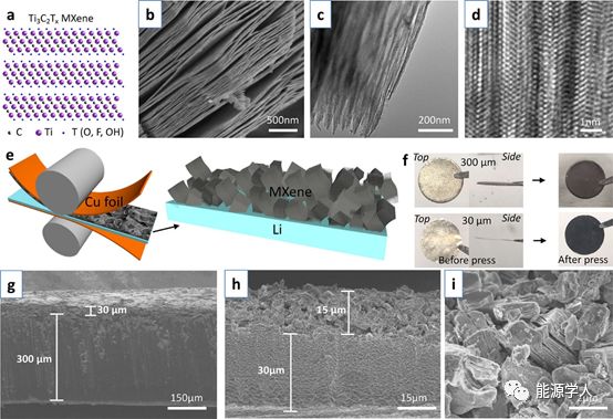
Figure 1 Preparation and morphology of ILC-Li electrode. (A) Atomic structure of Ti 3 C 2 T x -MXene; (b) SEM morphology of layered MXene stack; (c) TEM and (d) high-resolution TEM images of MXene; (e) Press on both sides to press it into a thin Li sheet; (f) Top and side views of 30μm and 300μm lithium sheet electrodes; (g) SEM cross-sectional morphology of 300μm and (h) 30μm ILC-Li electrodes; ) An enlarged SEM image of the cross section of the ILC-Li electrode.
The aluminum element was removed from the layered ternary carbide Ti 3 AlC 2 phaseby an acid etching process , and a Ti 3 C 2 T x -MXene laminated structure as shown in FIG. 1 a was prepared . After removing the aluminum element, the layered structure still exists, which can be proved by SEM (Figure 1b) and TEM (Figure 1c, d).Subsequently, the MXene stack was pressed onto the copper foil without further treatment by an adhesive / additive process to a design thickness of, for example, 15 μm (equivalent to 0.78 mg / cm 2 ). The inverted MXene was transferred to the Li sheet by applying force (Figure 1e). Using a controlled process, relatively smooth MXene layers were obtained on 300 μm and 30 μm lithium chips, respectively (Figure 1f).MXene-covered electrodes were obtained with a design thickness of 30 μm (Figure 1g) or 15 μm (Figure 1h). From the enlarged morphology in Figure 1i, it can be seen that the non-cyclic MXene stack is randomly scattered. Each stacked stack shows a large number of layer spacings, which provides enough space for lithium storage.
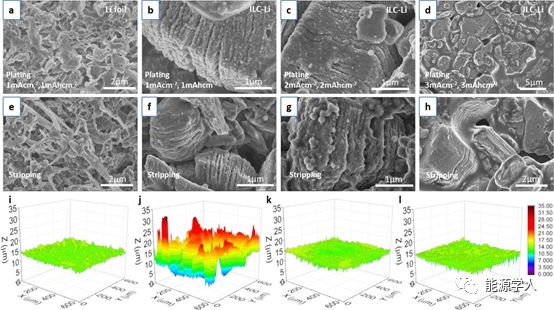
FIG 2 at different current densities, after 10 cycles, morphology and ILC-Li Li foil electrode in a lithium evolution cycle; mA in the current density. 1 / cm & lt 2 and mAh capacity. 1 / cm & lt two situations SEM images of lithium (a) deposition and (e) dissolution on lithium foil; ILC-Li electrode deposition (b, c, d) and 1-3 mA / cm 2 and 1-3 mAh / cm 2 respectively Dissolution (f, g, h) SEM image; 3D confocal surface roughness image of electrode (600 × 600 μm): (i) original lithium foil (j) original lithium foil after 10 cycles of lithium deposition (k) original ILC- Li electrode (1) Lithium is deposited after 10 cycles of the original ILC-Li electrode.
By analyzing the morphological evolution of the electrodes in a symmetrical battery during cycling under different current densities. It was found that under the conditions of a current density of 1 mA / cm 2 and a capacity of 1 mAh / cm 2 , after 10 cycles, a large number of moss / dendritic structures appeared on the lithium foil electrode (Figure 2a, e). Nucleation / growth of lithium is uneven. The 3D surface topography analysis in Figures 2i and j clearly shows that after cycling, the area roughness S q (root mean square height) increases sharply from 0.54 μm to 4.14 μm. In contrast, the ILC-Li electrode showed smooth deposition (Figure 2b) and dissolution (Figure 2f) morphology on the MXene interlayer. Even though the current density is 2 mA / cm 2(Figure 2c, g) and 3 mA / cm 2 (Figure 2d, h), after 10 cycles, the lithium deposition on the interface is relatively uniform, which is due to the MXene High specific surface area and high conductivity. The evolution of surface roughness measured with a confocal microscope further confirms the reliable deposition and extraction of Li. After cycling, S q decreased slightly from 0.92 μm (Figure 2k) to 0.69 μm (Figure 2l). It can be seen that the moss / dendritic lithium between the MXene layers is largely suppressed. A uniform lithium layer was formed on the MXene substrate, which greatly inhibited the generation of moss / dendritic lithium.
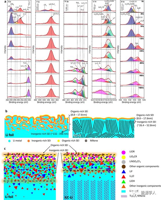
Figure 3 electrode XPS depth distribution map and SEI composition distribution map. (A) XPS depth distribution of the ILC-Li electrode after cycling three times at 1.0 mA / cm 2 and 1.0 mAh / cm 2 ; based on the XPS data, the (b) overall sum of the lithium foil and the ILC-Li electrode SEI layer (c) ) Component distribution diagram.
The SEI layer plays a key role in forming a dendrite-free, stable lithium electrode. The composition and distribution of SEI of ILC-Li electrode and pure lithium foil electrode were studied by XPS depth analysis. As shown in Figure 3a, on the electrode surface etched for 20s (depth 8.8nm), the C 1s peaks of 286.7 eV and 287.8 eV and the O 1s peaks around 530.4 eV correspond to CO and C = O, and the C 1s peak of 290.6 The F 1s peak at 688.5 eV corresponds to -CF 3. Therefore, the SEI film of the pure lithium foil electrode and ILC-Li electrode after the cycle is 8.8-17.6 nm from the top surface is rich in organic components (Figure 3b, c). . The range of inorganic components such asLiF, Li 2 CO 3 / LiOH, and Li 2 O is mainly in the range of tens of nanometers and hundreds of nanometers from the top surface (Figure 3a). The thickness of the inorganic layer of the ILC-Li electrode is about 26.4-52.8 nm, which is much thinner than the thickness of the inorganic layer at the surface of the lithium foil electrode 132-396 nm (Table S1 and Figure 3b, c). From the circulating ILC-Li electrode, we also found two strong peaks at 453.6 eV (Ti 2p) and 58.2 eV (Li 1s), corresponding to the Li-C x -Ti group (Figure 3a). This confirms that lithium was successfully interlayered into a MXene-lithophilic layer.
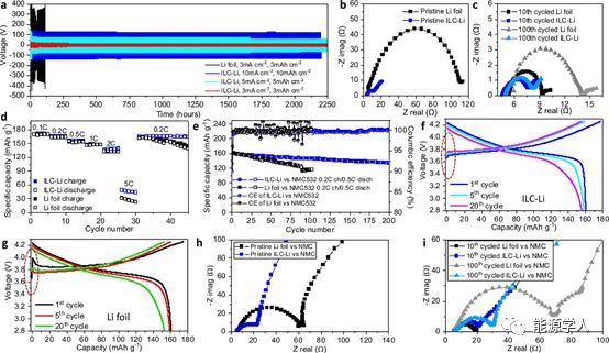
Figure 4 Electrochemical performance of a lithium foil electrode and an ILC-Li electrode symmetrical battery and a full cell matched with an NMC positive electrode. (A) ILC-Li (red, cyan, blue) electrodes and lithium foil (black) electrodes under different current density and capacity constant current cycling; (b) ILC-Li (blue) is not circulating in symmetrical batteries ) And EIS curve of Li-foil (black) electrode; (c) EIS curve of ILC-Li and Li foil electrode after cycling in symmetrical battery; (d) rate performance of battery from 0.1 to 10.0 C and NMC532; (e ) Cycle performance when the battery is charged at 0.2 C and discharged at 0.5 C. The specific capacity is calculated based on the discharge capacity of each cycle; under different cycles (f) ILC-Li / NMC532 and (g) Li-foil / NMC532 Voltage distribution; (h) uncirculated and (i) cyclic ELC curves of ILC-Li / NMC532 and Li-foil / NMC532 full cells, NMC532 load: 10 mg / cm 2 .
The electrochemical stability of the electrode during the cycle of lithium deposition / dissolution was investigated in a symmetrical battery. In the first 10 cycles, a low overpotential of about 35 mV was observed with an ILC-Li electrode at a current density of 3 mA / cm 2 and a capacity of 3 mAh / cm 2 (Figure 4a, red). Subsequently, the overpotential stabilized at 15-20 mV for 1125 cycles (2250h). At 5 mA / cm 2 and 5 mAh / cm 2 , the potential is maintained at about 80 mV (green) after an ultra-long cycle. Even with a high current density of 10 mA / cm 2 and a high capacity of 10 mAh / cm 2 , a relatively low overpotential (blue) of 120 mV can still be obtained after 2200 h.The lithium foil electrode showed an initial overpotential of more than 350 mV, reaching 1.0 V only after 100 cycles (Figure 4a, black).
Good electrical conductivity, large and uniform surface, and fewer SEI films result in lowered barriers (low overpotentials) to form reliable lithium nucleation / growth in the MXene matrix. However, because the surface of the lithium foil is rough, the specific surface area is small, and a thicker SEI is formed, which leads to uneven lithium nucleation / growth and a larger potential barrier (high overpotential), which also increases the possibility of dendrite formation Sex. Electrochemical impedance spectroscopy (EIS) was used to measure the interfacial resistance between ILC-Li and lithium foil electrodes. It is observed in the Nerst curve (Figure 4b) that the contact resistance of both electrodes is around 4.5 Ω. However, the transfer resistance of the ILC-Li electrode is 7.7 Ω, which is only about 7% of the lithium foil electrode‘s 107.5 Ω.From the perspective of stable SEI layer formation, the charge transfer resistance of the ILC-Li electrode was slightly reduced to ~ 3.2 Ω after 10 cycles, and decreased to ~ 3.4 Ω after 100 cycles (Figure 4c). For lithium foil electrodes, the charge transfer resistance is 4.1 Ω after 10 cycles and the charge transfer resistance is 8.4 Ω after 100 cycles. This change is mainly due to polarization caused by different SEI layer thicknesses at high frequencies.
With NMC532 as the positive electrode, the electrochemical performance and battery cycling performance of the full cell were tested. As can be seen from the rate capability in Figure 4d, batteries with ILC-Li electrodes and lithium foil electrodes show similar specific capacities at low charge and discharge rates. However, at high rates such as 2.0 C and 5.0 C, it is observed The capacity of the ILC-Li electrode is significantly higher. When the rate changed back to 0.2 C, the capacity of the ILC-Li electrode recovered 99.5%, while the capacity of the lithium foil electrode recovered only 85%. The fast lithium ion and electron transport speed in the ILC-Li electrode is the main reason for the better rate performance. The capillary force provided by the large surface area sandwich can improve the wettability of the electrolyte. As the electrolyte diffuses through sub-micron-sized pores and channels, this enhanced wetting can shorten the transmission distance of lithium ions. The battery capacity retention rate was also compared by cycling tests during 0.2 C charge and 0.5 C discharge (Figure 4e). The battery with ILC-Li as the negative electrode showed a Coulomb efficiency (CE) of 90% in the first cycle, and maintained a stable Coulomb efficiency of 99.6% in 200 cycles, while the lithium foil electrode showed after 30 cycles Significant fluctuations from 96% to 102%. With the ILC-Li electrode, the capacity retention rate reached 92% at the 100th cycle, and the capacity retention rate reached 83% at the 200th cycle, while using lithium foil, the capacity retention rate was only 72% after the 100th cycle.
As shown in Fig. 4f, the smooth voltage distribution of free potential absorption (dotted circle) of the full cell under different cycles indicates that the lithium nucleation / growth barrier on the MXene layer is reduced. In contrast, the apparent voltage jump at the beginning of a lithium foil electrode (Figure 4g, dotted circle) means that lithium nucleation / growth is uneven due to a large potential barrier. The results show that 0.78 and 1.56 mg / cm 2 lithium batteries exhibit similar low potential changes, indicating that lithium nucleation is caused by the smallest nucleation barrier.The total mass of the electrode was reclassified, and a load of 0.78 mg / cm 2 was selected. Electrochemical impedance spectroscopy (EIS) was used to study the interface resistance of full cells. Similar to the half-cells in Figure 4b and c, before the cycle, the contact resistance of the full-cell ILC-Li and lithium foil electrodes were both~ 4.9 Ω, while the transmission resistance of the ILC-Li electrode was lower at 17.9 Ω, the transmission resistance of the lithium foil is 58.2 Ω (Figure 4h). The charge transfer resistance of the ILC lithium battery at the 10th cycle was 16.3 Ω, the charge transfer resistance at the 100th cycle was 24.4 Ω, and the charge transfer resistance of the lithium foil battery increased from 13.8Ω at the 10th cycle to 63.6 Ω at the 100th cycle (Figure 4i). The thinner the SEI layer on the ILC-Li electrode, the lower the transfer resistance of the full cell.
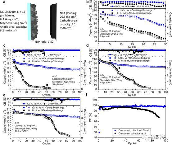
Figure 5 Battery performance of a full cell under electrolyte-poor conditions. (A) ILC-Li / NCA full battery design. Use (b) 2.5, (c) 5.0, 7.5, and (e) 10.0 μL / mAh electrolyte, and use ILC-Li / NCA (blue) and Li-foil / NCA (black) batteries at 0.2 C Ability to cycle. The thickness of the lithium body is 30 μm, and the capacity is based on the specific discharge capacity. NCA loading: 20.5 mg / cm 2 ; (f) Coulomb efficiency curves of MXene-Cu / Li and Cu / Li batteries at 0.5 mA / cm 2 and 1.0 mAh / cm 2 .
To obtain high battery energy density, the cathode area capacity (N / P) ratio is controlled to within 1.52 use. 5 [mu] lean electrolyte L / mAh, i.e. 6 g / Ah of an electrolyte / volume (E / C) ratio. In thin ILC-Li / NCA and Li-foil / NCA assembled battery, respectively, 2.5 to 10 [mu] Test full cell performance (FIG. 5b-e) under the L / mAh lean conditions of the electrolyte. In the 2.5 [mu] L / mAh (E / C ratio: 3.0 g / Ah) of a small amount of electrolyte, the capacity ratio of ILC-Li / NCA cell Li-foil is much higher than the attenuation / NCA cell slower (FIG. 5B), the energy The density is as high as 366.6 Wh / kg (Table S2). When using 5.0 [mu] When L / mAh electrolyte used in the ILC-Li battery capacity retention ratio after 100 cycles greater than 75%, the energy density of 283.6 Wh / kg, L lithium foil was used only in the capacity of 30 cycles After dropping to below 10mAh / g (Figure 5c). When adding more 7.5 [mu] L / mAh (Figure 5d) and 10.0 [mu] When L / mAh (Fig. 5e) electrolyte battery having ILC-Li electrode showed retention of greater than 87% in 100 cycles. After 70-80 cycles, the capacity of the lithium foil battery dropped to almost zero.
In order to study the lithium loss caused by inactive lithium consumption during the lithium deposition / dissolution cycle, the coulombic efficiency of MXene-Cu / Li and Cu / Li batteries was tested at 0.5 mA / cm 2 and 1.0 mAh / cm 2 (Figure 5f). During 100 cycles, the average CE with MXene is higher than that of pure copper foil, which indicates that the capacity loss is much smaller, especially after 80 cycles (Figure 5f).The main irreversible lithium consumption is caused by the repeated formation of SEI, mossy / dendritic Li growth, and "dead lithium" wrapped by SEI. Multiple inactive lithium consumption and electrolyte consumption forming a thick SEI layer make the lithium foil electrode Faster capacity loss. However, the highly reversible lithium deposition / extraction through the 2D MXene structure greatly reduces the consumption of dead lithium and electrolyte by forming a thin SEI layer, resulting in high CE.
Ti 3 C 2 T x -MXene, as one of the most popular two-dimensional materials, has a unique laminated structure. Due to the large surface area and flexible expansion of the membrane, the storage capacity of lithium in the interlayer channels is large.According to reports, the theoretical capacity of the original MXene can be as high as 447.8 mAh / g, and MXene has good metal conductivity and lithium affinity, which promotes the storage and ion transport of lithium in interlayer channels. MXene‘s excellent Li + / e conductivity results in a smaller contact / transfer resistance, which greatly reduces the barrier to lithium nucleation / growth and reduces the formation of SEI. Reduction in the location of SEI surface defects may slow down the formation of irregular pits, leading to uniform peeling and delaying the formation of moss / dendritic lithium. By having the smallest potential barrier, the conductive surface of each layer is the preferred location for uniform lithium nucleation / growth, resulting in a significant reduction in local current density and delaying the dendrite to reach "Sand‘s time". In addition, laminated structures offer some unprecedented physical and electrochemical advantages in LIBs. First, the layer-by-layer structure of MXene with a large interlayer distance (> 1.0nm) allows Li + to diffuse rapidly. Appropriate adsorption energy on the surface of MXene facilitates the rapid migration of Li + .Second, industrially available MXene has better wettability to the lithium metal body, thereby reducing contact resistance.
【Conclusion and Outlook】
In this paper, ultra-thin lithium metal electrodes were prepared using self-stripping MXene. High-reliability lithium deposition / dissolution can be achieved even at a large current density of 10 mA / cm 2 . The good conductivity of the two-dimensional laminated structure and the large available space minimize the local current density and regulate the growth of lithium, which results in the uniform deposition / extraction of lithium with less formation of unstructured SEI. At the same time, the two-dimensional confinement effect between layers further inhibited the formation of dendrites. Symmetric cells and full cells using ILC-Li electrodes show high capacity retention rates under high charge and discharge rates and long cycles. Specifically, the energy density matched by the full cell of NCA and low N / P ratio is as high as 366.6 Wh / kg. Provides an industrially available, safe, lithium metal negative electrode with an energy density of more than 400 Wh / kg for lithium-NMC / NCA, lithium sulfur, and lithium air batteries.
Xi Chen, Mingwei Shang, Junjie Niu *, Inter-layer-calated Thin Li Metal Electrode with Improved Battery Capacity Retention and Dendrite Suppression, Nano Lett. 2020, DOI: 10.1021 / acs.nanolett.0c00201
Source: Energy Scholar