
hotline:
17715390137
Tel/Wechat:
18101240246 (Technology)
0512-68565571
Email:mxenes@163.com (Sales Engineer)bkxc.bonnie@gmail.com
Scan the code to follow or search the official account on WeChat:
2D Materials Fronrier After paying attention,
click on the lower right corner to contact us,
Enter enterprise WeChat.
Professional Services Online

【Research Background】
Lithium batteries are today‘s most promising means of mobile energy storage and play a key role in the transition from fossil fuels to renewable energy. However, in order to meet the energy density requirements of electric vehicles, researchers must further increase the energy density of the battery. To achieve this goal, there are three options: (1) Through the optimization of battery engineering, reduce dead volume and weight; (2) develop new active materials; (3) develop solid-state batteries.
The concept of thin-film solid-state batteries has a history of nearly 50 years. However, due to the lack of highly conductive solid electrolytes (SEs), this research topic has almost been forgotten. In 2011, as the Kanno research team discovered a new ion conductor phase (Li10GeP2S12), it was refocused. In recent years, solid-state batteries have become a hot topic in the industry and research fields. However, current solid-state batteries still face a series of problems, such as unstable interface, structural damage during cycling, and lithium dendrite growth.
As for the cathode materials of solid-state batteries, the common choice is to use high-voltage cathode materials to maintain high energy density, including layered, spinel or olivine oxides. However, the redox potential of these oxides far exceeds the thermodynamic stability of ion-conducting sulfides. In addition, there is a difference in electrochemical potential between the positive electrode material and the solid electrolyte, which will cause a chemical reaction between the two or the formation of a lithium depletion layer at the interface when they are in contact, which will damage the battery performance.
[Article Introduction]
As a design strategy for high energy density cathode materials, anionic redox chemistry has attracted attention in the field of energy storage. The team of Jean Marie Tarascon, a professor at the College-de-France and an academician of the French Academy of Sciences, has accumulated a wealth of expertise in the solid-state chemistry of "real" and "model" anionic redox compounds, and a previous work A new type of high-capacity lithium-rich sulfide Li1.13Ti0.57Fe0.3S2 (theoretical capacity 261 mAh g-1, referred to as LTFS) is proposed, which has cation and anion redox activity, involving Fe2+/3+ and S2-/Sn- respectively (N<2). In this paper, the author studied the performance of the material when used as an all-solid-state lithium metal battery.
[Article Interpretation]
1. Characterization of LTFS
Figure 1 shows the scanning electron microscope (SEM) image and synchrotron radiation X-ray diffraction (SXRD) image of Li1.13Ti0.57Fe0.3S2 powder. The photo shows the morphology of spherical particles ranging in size from 5 to 20 μm (Figure 1a, b). The SXRD pattern (Figure 1c) shows that the powder is a single crystal phase with no residual impurities. According to Rietveld refinement, the crystal structure of LTFS is hexagonal phase (R3̅m space group), lattice parameters a=3.53Å, c=18.09Å, this structure is similar to the well-known lithium-rich layered Li1+yM1-yO2 phase, but has Larger structural unit to accommodate larger S2-ligands. Note that the structure is cationic disordered, and Fe atoms are located at the same position as Ti/Li in the metal layer (Figure 1d).
Finally, the LTFS/β-Li3PS4 (70/30wt%) composite was heated at 200°C to test the XRD and dc conductivity before and after heating to verify the compatibility of LTFS and the solid electrolyte β-Li3PS4. Rietveld refinement results of XRD data show that after heating, only LTFS and β-Li3PS4 are present in the composite. In addition, the conductivity after heat treatment also remained constant, about 5×10⁻³ S cm-1 (Figure 1f).
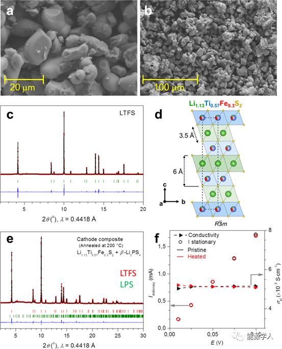
Figure 1 (a, b) Scanning electron micrograph of Li1.13Ti0.57Fe0.3S2 (LTFS); (c) SXRD pattern and Rietveld refinement of LTFS; (d) Crystal structure of LTFS; (e) LTFS/β- SXRD pattern and Rietveld refinement of Li3PS4 (70−30 wt %) composite heated at 200°C for 5 days; (f) steady-state current and dc conductivity of LTFS/β-Li3PS4 (70−30 wt %).
2. LTFS || InLi All Solid State Battery
In order to test the performance of LTFS as a solid-state lithium battery cathode material, the researchers first chose InLi alloy as the anode. This alloy is less reducible than pure Li (0.6V vs Li/Li+), so it can ensure better interface stability. Figure 2a shows the SEM image and cross-sectional EDS image of the newly assembled LTFS+β-Li3PS4 (70-30 wt%)|β-Li3PS4|InLi in a fully charged battery. Three dense layers can be distinguished from bottom to top, corresponding to InLi negative electrode, β-Li3PS4 solid electrolyte and LTFS+β-Li3PS4 positive electrode. The transition from the positive electrode to the solid electrolyte interface is smooth, indicating good layer-to-layer contact. In addition, Ti and P are uniformly distributed in the positive electrode, showing a uniform LTFS/β-Li3PS4 composite material. For the negative electrode side, its thickness is about 80 μm.
Figure 2b describes the constant current charge and discharge curve of solid-state lithium battery LTFS+β-Li3PS4 (70-30wt%)|β-Li3PS4|InLi at C/25 and different temperatures, as well as the discharge specific capacity and coulomb efficiency (Figure 2c) . At the first charge, it showed a long redox plateau at 2.1 V. Subsequently, the battery is cycled and has good reversibility and capacity retention.
The dotted line in the figure shows the polarization during the cycle, which is determined as the charge-discharge voltage difference at the 120 mAh g-1 position. The results show that it decreases with increasing temperature. Significant capacity loss was observed in the first cycle (coulombic efficiency 69%, irreversible capacity 50 mAh g-1). Starting from the second cycle, the specific capacity at room temperature is 120 mAh g-1, and further increases to 140 mAh g-1 at 100 ℃. However, this is still only 54% (C/20) of the reversible capacity in liquid batteries. This difference in capacity can be attributed to the fact that liquid electrolytes provide better wettability of active materials and greater ionic conductivity than solid electrolytes.

Figure 2 LTFS + β-Li3PS4(70-30 wt %)|β-Li3PS4|InLi battery. (A) SEM picture and EDX element distribution of battery cross section; (b) constant current charge and discharge curve; (c) discharge capacity and coulomb efficiency at different temperatures.
In order to evaluate the stability of the positive electrode/solid electrolyte interface, after the first, second and third cycles, the EIS of the whole battery was measured in the original and discharged state. The corresponding Nyquist curve is shown in Figure 3. The interface resistance of the positive electrode/solid electrolyte is between 50-70Ω. These resistance values are very small. Therefore, we can be sure that the interface resistance between LFTS and solid electrolyte is low, and no buffer layer is needed. This is related to the fact that both are sulfur-based compounds. In addition, compared with oxides, LTFS has a lower operating voltage and does not form a space charge layer. Therefore, low-voltage/large-capacity cathode materials can be used as a strategy to alleviate the problem of the cathode/solid electrolyte interface without sacrificing energy density. In addition, these results rule out the possibility that the irreversible capacity in the first cycle comes from the LTFS interface reaction.
However, the calculated solid electrolyte resistance is 529 Ω, which increases to 640-670 Ω after cycling, which suggests that the decrease in performance may be related to the volume change (53%) of the InLi anode during cycling.
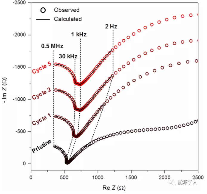
Figure 3 Nyquist impedance curve of LTFS + β-Li3PS4 (70-30 wt%) | β-Li3PS4 | InLi battery.
3. LTFS || Li all solid state battery
As mentioned earlier, compared with current technology, one of the main advantages of solid-state lithium batteries is the increase in energy density. In this case, a lithium alloy negative electrode is impractical because of the lower voltage of the assembled battery (compared to lithium). In addition, alloy metals are heavy and expensive (such as indium). Because LTFS has good performance in solid-state lithium batteries assembled with InLi alloy anode, the author further introduces lithium metal as the anode to move towards a practical all-solid-state system.
Figure 4a is an all-solid-state LTFS+β-Li3PS4 (70-30wt%)|β-Li3PS4|Li battery. The cross-sectional view shows a dense and continuous laminate structure with no visible cracks and good contact between the layers. Figure 4b shows the constant current charge and discharge curves for the first and tenth cycles, and Figure 4c shows the discharge specific capacity and coulomb efficiency for the first 10 cycles. The voltage-capacity curve shows that the battery has low polarization (85 mV at 120 mAh g-1), no capacity loss, and a coulombic efficiency greater than 99%. After 10 cycles, a reversible capacity of 214 mAh g-1 can be obtained, which is equivalent to 83% of the theoretical capacity. In addition, LTFS || Li has no reversible capacity loss in the first lap, and is less polarized than LTFS || InLi batteries, and has higher reversible capacity.
In addition, the impedance of the battery was also tested in the article, and the results showed that the resistance of the solid electrolyte did not increase, and the evolution of the positive electrode/solid electrolyte interface was negligible, which was different from the result of using an InLi alloy negative electrode. This shows that the reliability of the widely used InLi alloy as the negative electrode of the experimental model is questionable. In particular, in the system, a large volume change (∼53%) occurred during the alloying process, which may lead to poor contact between the negative electrode and the electrolyte.

Figure 4 LTFS + β-Li3PS4 (70-30 wt %) | β-Li3PS4 | Li battery. (A) SEM picture and EDX element distribution of cell cross section; (b) constant current charge and discharge curve; (c) discharge capacity and coulomb efficiency.
4. LTFS as NMC/β-Li3PS4 buffer layer
The above has proved the excellent performance of LTFS as a cathode material in solid-state lithium batteries, which depends on its high stability during cycling. At this time, the author further proposed whether it is possible to use LTFS as a protective coating for lithium intercalation oxide cathode materials. In this case, LTFS will replace the currently used electrochemical inert coatings (LiNbO3, Al2O3) and at the same time serve as an active buffer layer to reduce the interface resistance of NMC/β-Li3PS4. The author chose NMC 622 (particle size: d50 12μm) as the active substance and mixed with LTFS. Figure 5 shows the EDX map and line analysis on LTFS coated NMC particles. The scanning elements are P, Ti/Fe and O, which respectively illustrate the existence of β-LPS, LTFS and NMC.
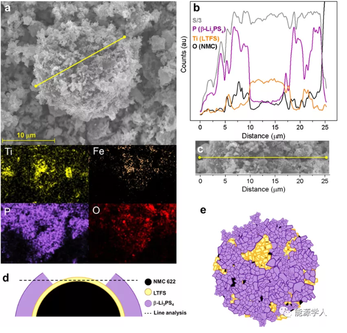
Figure 5 (a) SEM picture of NMC particles in NMC622/LTFS/β-LPS (63:7:30 wt %) and corresponding (b) (c) EDX line scan; (d) (e) schematic diagram of composite particles .
In order to prove the author‘s idea, two all-solid-state batteries (called proof A and proof B) were assembled in the experiment. The first one is LTFS-free, and the latter adds 7% LTFS to the positive electrode.
Proof A: NMC 622/β-Li3PS4(70:30 wt %) | β-Li3PS4|InLi.
Proof B: NMC 622/LTFS/β-Li3PS4(63:7:30 wt %) | β-Li3PS4|InLi.
Figure 6 shows the first constant current charge-discharge curve of the two batteries and the discharge capacity of 10 cycles. Compared with the battery using only NMC 622, the battery containing LTFS has improved performance in terms of reversible capacity and overvoltage. These results prove that the resistance of the positive electrode/solid electrolyte interface of proof B is lower.

Figure 6 The charge-discharge curve and cycle performance of the two batteries (C/50, room temperature).
【in conclusion】
In this work, the author proposed Li1.13Ti0.57Fe0.3S2 (LTFS) as a new lithium battery cathode material for the assembly of all solid-state lithium batteries. When InLi and Li negative electrodes were used to test their performance in solid-state batteries, LFTS showed good cycle performance and capacity stability. In particular, the EIS measurement proved the good stability of the positive electrode/electrolyte interface in both cases. In addition, at room temperature, without any coating or conductive agent, the performance (capacity and voltage polarization) of the LTFS and lithium metal assembled battery is excellent. In contrast, when an InLi alloy negative electrode was used, a significant capacity loss was observed in the first cycle, which indicates the reliability of InLi alloy as a negative electrode material in solid-state batteries.
Finally, the author added LTFS to NMC‘s all-solid-state cathode, and the results showed an improvement in the cathode/electrolyte interface. Therefore, the article suggests the use of lithium active sulfide as an alternative to the coating of positive electrode materials in solid-state batteries.
Florencia Marchini, Sujoy Saha, Daniel Alves Dalla Corte, and Jean Marie Tarascon. Li-Rich Layered Sulfide as Cathode Active Materials in All-Solid-State Li−Metal Batteries. ACS Appl. Mater. Interfaces, 2020. DOI: 10.1021/acsami .9b22937
This information is sourced from the Internet for academic exchanges only. If there is any infringement, please contact us to delete it immediately.

| Reminder: Beijing Beike New Material Technology Co., Ltd. supplies products only for scientific research, not for humans |
| All rights reserved © 2019 beijing beike new material Technology Co., Ltd 京ICP备16054715-2号 |